
The Tips and Tricks of Soldering to build Chronic Implants for in vivo Electrophysiology in Rodents
Tips for neuroscientists working on in vivo electrophysiology in rodents. Know how to solder your wires.

Imagine you have arrived to a lab to do a very exciting project in in vivo electrophysiology in freely behaving mice. For this project you need to build the implants. However, you have never touched a soldering iron in your life let alone solder two cables together. What do you do? How does it work? How do you know where to start? How do you know you soldered those two cables properly?
Read this post and learn all you need to know about soldering to build your own implants. From creating your own EEG screws to know how to troubleshoot in moments of need.
Not learning how to properly solder will make you waste time, run into problems, get noise in your signal and will bring you lots of frustration!
You happen to be in the right place for a great start to learn the tips and tricks of soldering. With the proper introduction to soldering and a bit of practice you will master it
Why do you need to solder properly?
First things first, do not under-appreciate the value of good soldering!
Soldering is done in in vivo ephys to connect the pieces that will "catch" the electric signal of the brain and transmit it to your recording system.
If you have been navigating for some time in the world of in vivo ephys, you are more than familiar with noisy signals. Noise can totally compromise your data analysis to the point that you may have to discard that data and your 6h experiment has to be thrown out the window. And who wants that?
One source of noise is bad soldering. And bad soldering not only causes noise. If your ground screw is not well soldered and therefore not well connected to your recording system, you will only see 50 Hz noise. Hence, your motivation to become a master of soldering.
What do you need for soldering?
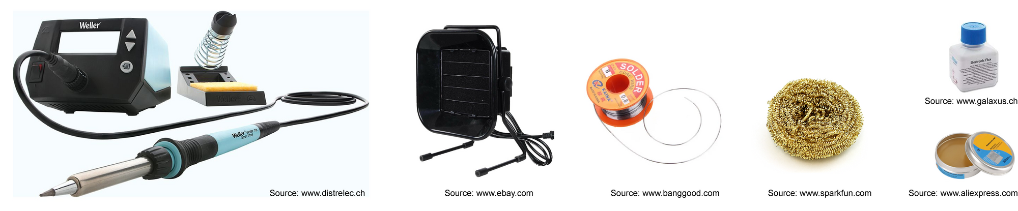
The materials are:
- Soldering iron. This is the hot piece of iron that you will use to melt the solder and connect the different components (eg. solder the EEG screw to a cooper wire and the cooper wire to a gold pin). Don't forget the stand to hold it and the temperature controller.
- Solder. This material is usually a metal alloy that will melt and connect your pieces. In the field of in vivo ephys, we usually use tin.
- Damp sponge. This is a sponge that you need to wet with water and will help you clean the tip of the soldering iron. It can be substituted by a brass sponge, which is actually recommended over the conventional sponge because it does not cause expansion and contraction of the tip of the soldering iron that the cold water in the damp sponge does.
- Fume extractor. A fume extractor is like a vacuum cleaner of the air. It consist of a ventilator that sucks the air and passes it through a carbon filter. We need this because melting metals releases toxic fumes that harm your lungs and eyes. Do not forget to turn on your fume extractor!
- Soldering gel. This gel is used in the areas where you wish to apply the solder. It helps to homogeneously transmit the heat of the soldering iron to the material so that you don't need prolonged contact time. You can find it as a paste or as a liquid.
Main steps for proper soldering
Proper soldering is easy when you know how to do it. Follow the next steps and you cannot do wrong!
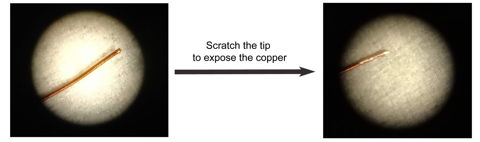
- Use tweezers to remove the plastic that surrounds the wire or scratch the tip of the wire with a scalpel if there is no plastic coating.
- Melt some solder using the soldering iron. The solder will stay on the tip of the soldering iron.
When you see you have a small drop on the tip of the soldering iron, stop.
- Apply a bit of soldering liquid/paste to the wire.
- If you have a wire: drag the wire end from the top to the bottom of the soldering iron tip.
If you have a screw or golden pin: put the soldering iron in contact with it (you don't need longer than 1 second to leave a droplet on the screw/pin)
- Put in contact the parts that have been covered in solder.
- Use the soldering iron to connect the tin of both components.
- Check the soldered connection is strong enough by gently pulling both components apart from each other.
Tricks for proper soldering
Like many other techniques, soldering also has its tricks!
These are:
- Always use soldering gel. This will facilitate that the tin attaches to screw/wire because heat is transmitted more rapidly and homogeneously.
- Use very high temperatures. Using high temperatures decreases the time that you need to put the soldering iron in contact with the wire/screw. Plus, highly increasing the temperature of the screw/wire lets the tin flow better and establish a better connection with your component of interest. Minimum recommended temperature = 400°C.
- Clean the soldering iron often to avoid residues. Oxidation and melted plastic sometimes can accumulate on the tip of the soldering iron and can compromise the quality of the connections between components.
- Do not use large blobs of solder. This is just going to bother the animal and add weight to the implant. Plus, you don't increase the conductivity and you may pick up noise.
- Add solder to all the points or areas that you want to connect. This will help to connect two components very quickly.
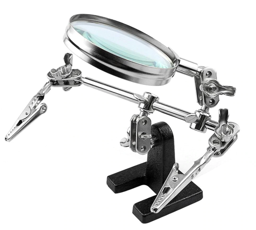
- Use a third and fourth helping hand when necessary. Eventually you will realize that sometimes your two hands will not be enough. Make use of helping hands and blu tack to fix wires, screws and any other part you wish to solder.
I would advise you to practice soldering before you start working with the final components of your implants.
Start with large wires and see yourself how the solder behaves once it melts and flows on the wire.
Experiment with high and low temperature as well as with different quantitites of soldering gel.
Once you have a first experience, gradually move to smaller wires.
You can find good images on how solder behaves on this video.
Tips on wires and screws
Wires
When you are working on in vivo ephys you will encounter three main types of wires:
- The ones you need to connect your screws to the electronic interface board (EIB).
- The ones you need to measure the electromyogram (EMG)
- The ones you will put inside the brain to measure spikes or local field potentials.
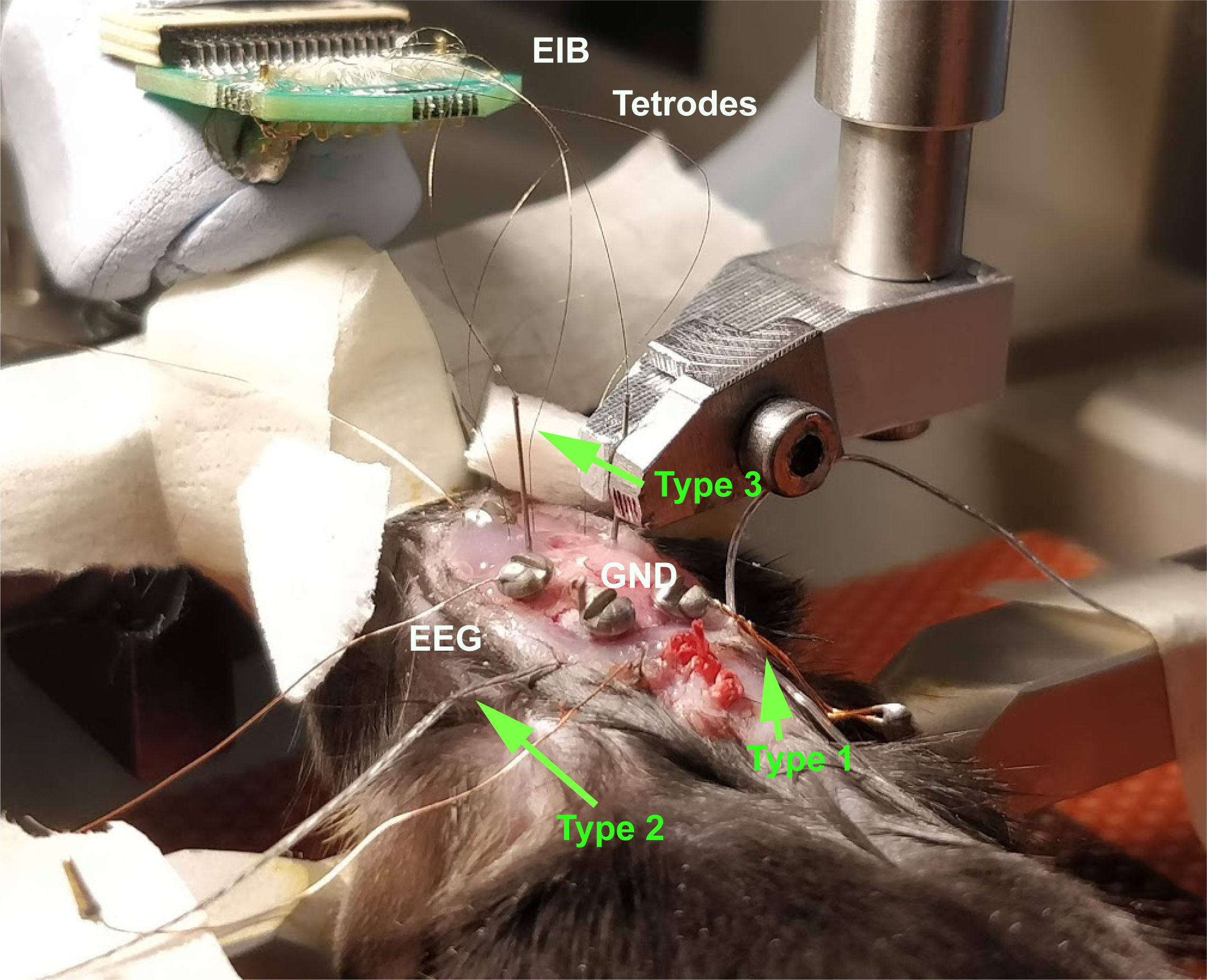
Type 1 - Wires for the screws. In general, cooper wire is used to connect the EEG and ground (GND) screws to the EIB or connector. If you are using an EIB, these cooper wires in fact connect the screws to the golden pins that will be pinned into the EIB.
Copper is commonly used because its conductance is good and is very cheap compared to other high conductive materials (eg. silver).
Working with copper wires is fairly easy. Scratch both ends of the wire to remove the layer that surrounds the copper. Don't scratch a too large area, otherwise you will be facilitating contamination of the signal from another wire when you put everything together. Dip both ends of the wire into the soldering gel and coat both ends with tin. To do so, apply some tin at the tip of the soldering iron. Then, take the cooper wire end and drag it from the top to the end of the soldering iron tip as you have seen in Video 2.
Type 2 - EMG wires. For EMG recordings, people in the field use aluminium or stainless steel wires in a wide range of diameters. Independently of the material and the width, most of these wires come with a layer of transparent plastic around it. You can easily rip the plastic apart using tweezers. Then the same procedure described before applies: dip in soldering gel and add the solder.
You will see that some labs use EMG wires that are one single wire or that are multiple small wires together. In the latter case, first twist the wires when they are exposed and proceed with the steps mentioned earlier with one additional detail: Do let the tin flow in between the wires.
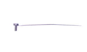
Type 3 - Wires to record brain activity. Unless you are using Neural Probes like the ones from Cambridge NeuroTech, you will most likely be using either tungsten wires or tungsten filaments. Tungsten filaments are used to make tetrodes and are so thin that they are directly pinned to the EIB with a gold pin. On the other hand, tungsten wires are thicker and not flexible and, in general, directly soldered to a connector. When working with tungsten wires, you need to first implant them in the brain and then solder them to the connector. For the soldering part it is very useful to add a couple of millimeters of the solder wire to the connector. When you have the right temperature at the soldering iron, put the tin in contact with the tungsten wire, in which you have previously put some soldering gel. With a short contact of the soldering iron with the tungsten wire and the solder of the connector, the tin will melt connecting the tungsten wire with the connector very rapidly.
Screws
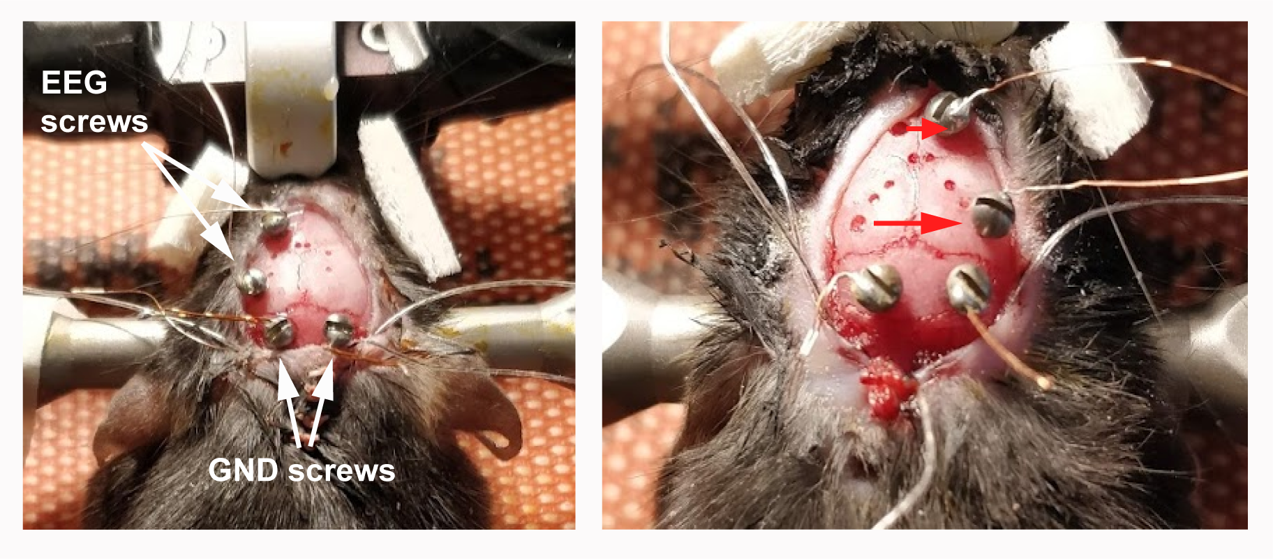
The screws that are used to measure the EEG and as a GND are usually made of stainless steel and have low impedance.
Stainless steel is a good material because its low resistance to current, which allows for a fast propagation of electrical signals.
Impedance is synonym to "obstruction of electrons" and it is measured in Ohms, like the resistance. Therefore, when a material has low impedance it means that this material lets the electrons flow without major obstructions. This is important for the EEG because the screw does not penetrate the brain, what means that the electric field that is able to capture is weak. For this reason, we do not want to put "obstacles" to the electric current that will travel from the brain to your recording system.
If you want to learn more about Impedance, have a look at the video Resistance, Reactance and Impedance and stay tuned for my next post on "What is Impedance when you work on in vivo Electrophysiology?".
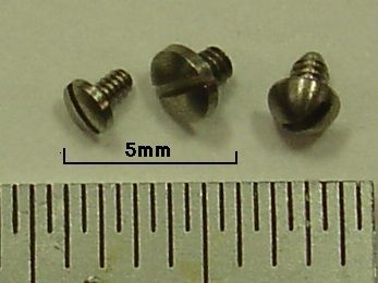
Most screws that you can buy to measure the EEG or as GND are ready to solder.
Nevertheless, some people claim that you need to pre-process these screws prior to solder. This process would prepare the surface for better adhesion with the tin and would increase impedance. They sometimes polish the screws with a dremel or sand paper. Some even use aggressive protocols with strong acids for this purpose.
In my experience I never encountered any problem of the tin not adhering to a screw. I also never had poor signal when the soldering was proper. For this reason I would not recommend adding an extra step to a process that is already long and complex.
Another option you have is to buy the EEG screw ready to use, like the ones that NeuroTech offers.
How to troubleshoot when things go wrong during surgery
You have all your components ready for implantation, the animal is ready in the stereotaxic frame and you are ready to begin implanting your EEG and GND screws.
Problem #1:
You notice before implantation that one screw has detached from the wire that will connect it to the connector!
In this case there is really no need to worry. Just solder the wire back to the screw. In general, it is not necessary to add more solder. Coat the end of the wire with the soldering gel, warm it up with the soldering iron and re-solder it to the screw.
Here is when you should not forget to clean it again! Isopropanol works very nicely to clean the leftover of soldering gel. Then I would recommend to use alcohol for sterilization and end it with a bath in saline. Dry it and its ready to implant.
Problem #2:
You have screwed your EEG and GND components into the skull and oh no! One wire has come off the EEG screw!
Well, I'm not going to lie. This is a tough one.
If you still have enough space on the skull, you can go for the following options:
- Option #1: Drill new holes for both EEG screws on the free hemisphere and record from the other hemisphere.
- Option #2: Drill a new hole for the EEG that has broken on the free hemisphere and record each EEG signal from a different hemisphere.
In both cases you can choose to take out the broken EEG screw or leave it in the skull. If you take it out, the damage of the skull will be more severe. But if you leave it there, it will add to the additional weight the animal has to carry on the head.
Now, if it happens that you don't have extra space on the skull, there are two ways to go.
- Option #3: Unscrew the broken EEG, repair it and screw it back. Here you must be extra careful because the hole has become larger and the screw will not sit firmly on the skull when you put it back. Be sure that you attach the EEG firmly to the skull with glue or dental cement before proceeding. Failing to ensure a proper fixation of the EEG screw to the skull will be the source of very annoying noise.
- Option #4: Take the wire, coat the detached ending with the soldering gel and add solder to that end. Now you need to be precise to avoid frying the brain of the animal. Warm up the end of the wire that connects to the screw so that the solder melts and put it in contact with the solder that has been left on the screw. If you do it correctly, the solder on the EEG screw should melt and connect to the solder you have put new on the tip of the wire. However, I would not recommend this option, especially if you have not mastered soldering yet.
In any case, make sure beforehand that all your components are well soldered. It is as easy as to lightly pull the screw from the wire and check whether it still holds together (see Video 3).
A general recommendation is to avoid or minimize soldering during animal surgery. Besides from reducing your stress during the surgery and making it safer for the animal, it will also reduce the time of the surgery, which can have a big impact on the recovery of the animal.
Conclusion
Follow the advice on this post and you will save a ton of time next time you build your implant. Plus, you won't need to troubleshoot and you will eliminate one source of noise.
To summarize, the main take-home messages we have seen in this post are:
- Using soldering flux will facilitate the connection of the solder with your material of interest. (Video 2 and Video 4)
- Always put solder on the surfaces of the two objects you want to connect. (Video 2 and Video 3)
- Using high temperatures will decrease the time that you need to melt the solder and connect two objects.
- You have to let the solder melt on the multi-cable wire to create connections between all the wires.
- How to solder different types of cables. (Section: "Tips on wires and screws")
- In case you have not soldered properly and the EEG/GND breaks during surgeries, there are solutions! (Section: "How to troubleshoot when things go wrong during surgery)
Beware that I have shown you the examples I use in my research. Your lab may use other types of wires and material.
Happy soldering!